© Copyright© Copyright

Copyright © January 28th 1996 - 2012 ..... Brought to you by Unitech Electronics Pty. Ltd.


              A Variety of simple NE-555 timing circuits to " tinker " with.
              These are deliberately kept simple and yet functional.

Safety First is our priority- Be aware of 240V mains


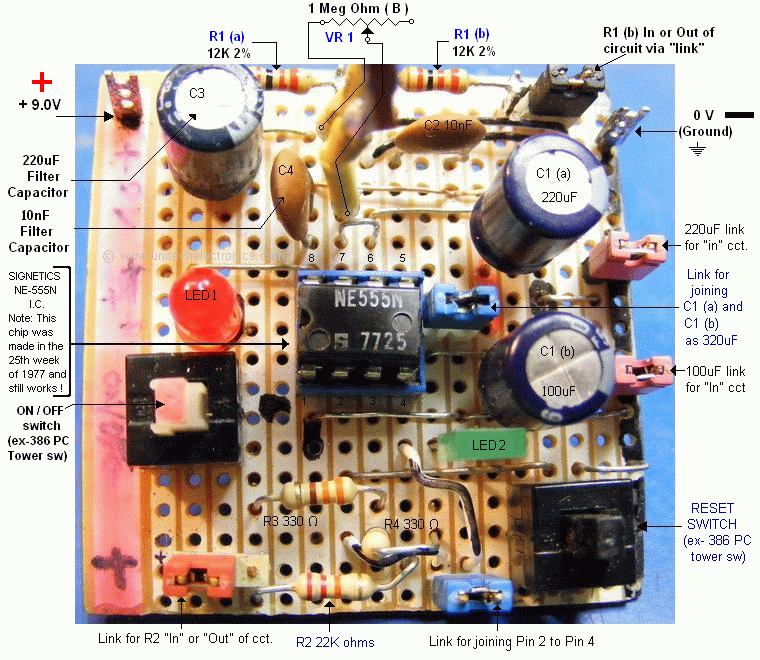
Please note, the NE-555 chip chosen for these experiments is in fact made by the original company, Signetics on the 
25th week of 1977.       This chip ( as of today September 23rd 2015 ) is 38 years old.   Not bad for a 38 year old chip 
fabrication technology and  manufacturing and still working today. We had 12 pcs of NE-555 chips (discovered) hidden
away in a static proof bag, in a box, since 1977, all were fully tested and found to be good. We also tried various other 
brands and arrived at similar conclusions, duly noting our results.  The brands tested were Motorola, Fairchild, R.C.A., 
National Semiconductor, MOS Technology and Texas Instruments, all tested chips displayed approximately the same  
characteristics to that of the original Signetics NE-555, that, as stated, was manufactured in the 25th week of 1977  . 
Based on testing of 30 mins per chip at room temperature 23 Deg C, we have to conclude this to be reliable data.        

Please, do bear in mind, the NE-555 is somewhat of a "noisey" chip while operating. It requires a few filter capacitors to
improve  the "noise" super-imposed on the power supply inputs and the use of 220uF and small 10nF capacitors reduce 
the "noise".  In removing this "inherent noise" produced by the NE-555, it should be noted that the use of smaller Tag     
Tantalum capacitors, perhaps to the order of 10µF , perhaps a ceramic capacitor  0.01µF and possibly a small µHenry   
choke to tame the noise.    We strongly suggest using a C. R. O. ( Cathode Ray Oscilloscope ) or a D. S. O.( Digital    
Storage Oscilloscope ) to observe the "noise" on your screen and applying a suitable remedy to remove the noise.        


4 NE555 CONFIGS.gif

 To the top of this page


NE-555 Front Breadboard Pic


 To the top of this page

Click on the NE-555 chip and watch the circuit above come to life !

NE-555-avi-VIDEO

Click on the NE-555 chip and watch the circuit above come to life ! 1.4 MB .avi file


 To the top of this page

NE-555 Rear Breadboard Pic


 To the top of this page

NE-555 Rear Breadboard Pic


 To the top of this page

NE-555 8 Min Timer CCT Pic


 To the top of this page

NE-555 2 minute timer


 To the top of this page

NE-555 12 minute timer


 To the top of this page

NE-555 5 minute 50 timer


 To the top of this page

NE-555 TIMED PLOTTED

NE555 Data


As the voltage ( in this case about 6.07 Volts ) reaches 2/3 of supply input to pin 8, ( 9.00V ) the NE-555 resets and pins       
6 and 7 revert back to zero Volts ( well, almost ) about 0.21 volts was measured.   Using C1a 100uF + C1b 220uF = 320uF   
+ VR1 1 Meg Ohm + R1 12K ohms. C1(a) = 100uF +C1(b) = 220uF (totalling 320uF) with VR1=1 Meg Ohm + R1=12K ohms,   
Reset time = 7 minutes and 8 seconds. Supply = 9.00 volts DC. Noted readings for straight C1 = 220uF with VR1 = 1 Meg Ohm
 + R1 = 12K ohms ( 1,012,000 ohms ) which equates to approximately 5 minutes and 50 seconds. The voltage = 9.00 volts DC.   


Click on the NE-555 chip and watch the circuit above come to life !

Click here --> NE-555-AVI-VIDEO <-- Click here

Click on the NE-555 chip and watch the circuit above come to life ! 1.4 MB avi file


 To the top of this page

Layout is Copyright © 1996 Onwards Unitech Electronics Pty. Ltd. ALL RIGHTS RESERVED.


Last updated: January 28th 1996
Added PDF access references: September 21st 2009.
Added 3 NE-555 pictures: September 23rd 2009.
Made this page " tablet compatible ": August 12th 2012.
Changed wmv to avi on October 21st 2015.

Safety First is our top priority- Be aware of 230V mains


E. &. O. E.

sales@unitechelectronics.com

Concept-Design-Layout-Copyright-Shipping